Fire Alarm Beam Smoke Detector
40+ years
Experience
400+ Patents
& LPCB
1,000,000+
projects
Global on site
after sale service
7x24h
response service
Table of Contents
TX7130: Fire Alarm Optical reflective Beam Smoke Detector
TX7130 is LPCB EN54 certified fire alarm beam smoke detector, auto aligning 8-100m coverage, beam smoke detector transmitter and receiver for warehouse, airport, station church etc.
Feature and Benefits:
- LPCB Approved, EN54 standard
- Built-in digital guide display & laser beam pointing
- Long distance: 8-100 meters.
- Easy sensitivity adjustment
- Built-in smartt microprocessor
- The self-diagnosis function to monitor for internal faults
- Intelligent algorithm automatic compensation
- Fire and fault-interfacing relays
Technical Datasheet
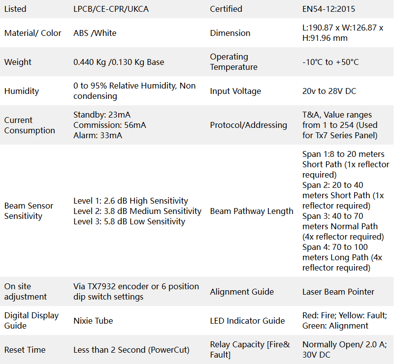
| Listed | LPCB/CE-CPR/UKCA | Certified | EN54-12:2015 |
| Material/ Color | ABS /White | Dimension | L:190.87 x W:126.87 x H:91.96 mm |
| Weight | 0.440 Kg /0.130 Kg Base | Operating Temperature | -10℃ to +50°C |
| Humidity | 0 to 95% Relative Humidity, Non condensing | Input Voltage | 20v to 28V DC |
| Current Consumption | Standby: 23mA Commission: 56mA Alarm: 33mA | Protocol/Addressing | T&A, Value ranges from 1 to 254 (Used for Tx7 Series Panel) |
| Beam Sensor Sensitivity | Level 1: 2.6 dB High Sensitivity Level 2: 3.8 dB Medium Sensitivity Level 3: 5.8 dB Low Sensitivity | Beam Pathway Length | Span 1:8 to 20 meters Short Path (1x reflector required) Span 2: 20 to 40 meters Short Path (1x reflector required) Span 3: 40 to 70 meters Normal Path (4x reflector required) Span 4: 70 to 100 meters Long Path (4x reflector required) |
| On site adjustment | Via TX7932 encoder or 6 position dip switch settings | Alignment Guide | Laser Beam Pointer |
| Digital Display Guide | Nixie Tube | LED Indicator Guide | Red: Fire; Yellow: Fault; Green: Alignment |
| Reset Time | Less than 2 Second (PowerCut) | Relay Capacity [Fire& Fault] | Normally Open/ 2.0 A; 30V DC |
Optical Beam Detector Fire Alarm Working Principle
This intelligent reflective long range smoke beam detector consists of a laser transmitter, a laser receiver, and 1 to 4 reflectors. This TX7130 addressable beam smoke detector that works at night is good. Its working principle is as follows:
1. The transmitter emits a laser beam.
2. The reflector reflect the laser beam emitted by the transmitter.
3. The receiver detects the laser beam reflected by the reflector.
4. When smoke or particles obstruct the laser reflection, the receiver uses algorithms to determine whether a fire has occurred or if environmental interference exists.
5. The liner beam detector triggers an alarm signal, which is then handled by professionals.
Why does it specify “1 to 4 reflectors” instead of a fixed number?
This is because this intelligent reflective beam smoke detector offers four selectable working ranges, each corresponding to a different number of reflectors. The following is an in-depth explanation of this topic:
Beam Smoke Detector Coverage Area
Correlation Between Reflector Quantity and Working Range
The Tanda TX7130 fire alarm beam detector’s design optimizes reflector configuration based on detection distance:
1, Short-range mode (e.g., 8–20m):
Utilizes 1 reflector to form a direct laser reflection path.
Suitable for confined spaces where a single reflector ensures minimal signal loss.
2, Medium-range mode (e.g., 20–40m):
Employs 2 reflectors to create a multi-bounce reflection path.
Reflectors are positioned at angles to extend the effective detection distance while maintaining signal stability.
3, Long-range mode (e.g., 40–70m):
Requires 3 reflectors to compensate for increased beam divergence.
The triangular reflector arrangement enhances signal aggregation and reduces environmental interference.
4, Ultra-long-range mode (e.g., 70–100m):
Utilizes 4 reflectors in a quadrilateral configuration.
This setup maximizes reflection efficiency, enabling reliable detection over extended distances while minimizing false alarms from dust or vibrations.
| Working Range | Reflector Quantity | Application Scenario |
|---|---|---|
| 8–20m | 1 | Server rooms, small warehouses |
| 20–50m | 2 | Supermarket aisles, office corridors |
| 50–80m | 3 | Industrial halls, large exhibition spaces |
| 80–100m | 4 | Airports, stadiums, hangars |
Beam Smoke Detector Installation Details
Mounting Preparation
This beam detector must be installed, commissioned and maintained by a qualified or factory trained service personnel. The installation must be installed in compliance with all local codes having a jurisdiction in your area or BS 5839 Part 1 and EN54.
Note: The device component within the device is vulnerable specially the reed switch. It is advisable to use the magnetic tool when needed to prevent physical damage.
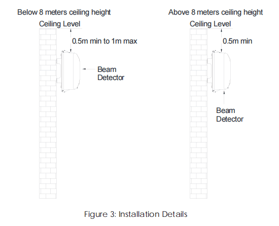
1. Under flat spare area. If the ceiling height is less than 8 meters, the beam detector should be installed 0.5 meter to 1 meter below the ceiling level. Refer to Figure 3.
2. Under flat spare area. If the ceiling height is more than 8 meters means beam detector maximum height 8m, the beam detector should be installed minimum of 0.5 meter below the top ceiling. Refer to Figure 3.
3. The chosen for the location should be clean and dry and not subject to shock, vibration or electro-statistic discharge, and free from glass wall, sunlight direction any reflective barrier.
4. Make sure that the beam path is free form obscuration against moving items.
Mounting of the Beam Detector
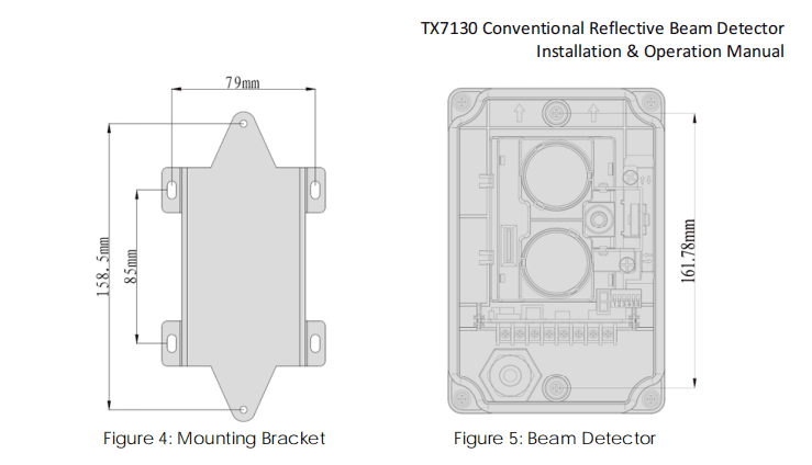
1. Using the supplied bracket, mark the position of the fixing holes.
2. Drill four holes and insert an 8mm wall plug into each.
3. Fix the mounting bracket to the wall using four ST4x30 screw. Refer to Figure 4.
4. Fix the detector base onto the bracket using two M4x12x10 standard screws. Refer to Figure 5
Reflector Mounting
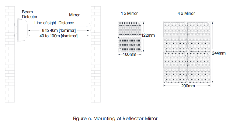
1. Depending on the project requirement, if the distance between the detector and the
reflector mirror is 8m-40m, install one reflector is enough; if the distance is 40m-100m, four
reflectors is required. Refer to Figure 6.
2. Mark the position of the fixing holes plastic expansion bolts.
3. Fix the reflector mirror using two ST4x30 standard screws, in the case of one-unit mirror, do the
same steps for other mirrors if required. Refer to Figure 6
For more information about mounting beam detector, please contact beam smoke detector manufacturers service team to get a installation manual.

Infrared Beam Smoke Detector Application
It can be used in unobstructed large spaces or venues with special requirements, such as shopping malls, halls, ancient buildings, large workshops, warehouses, tunnels, mezzanines and cock-lofts of all kinds of buildings, and any place where smoke appears before a fire breaks out, eg. China’s airport use beam detector.
It is worth mentioning that this beam detector can not only be integrated into the Tanda fire alarm system as a programmable smoke detector, but also be used as a standalone component with other brands fire alarm systems.
About Accessories
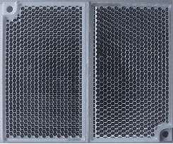
The reflector is a supporting product of TX7130 and is installed directly opposite to TX7130.
Features:
When the distance between the detector and the reflector is 8m-40m, only one reflector is needed
When the distance between the detector and the reflector is 40m-100m, four reflectors are needed
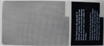
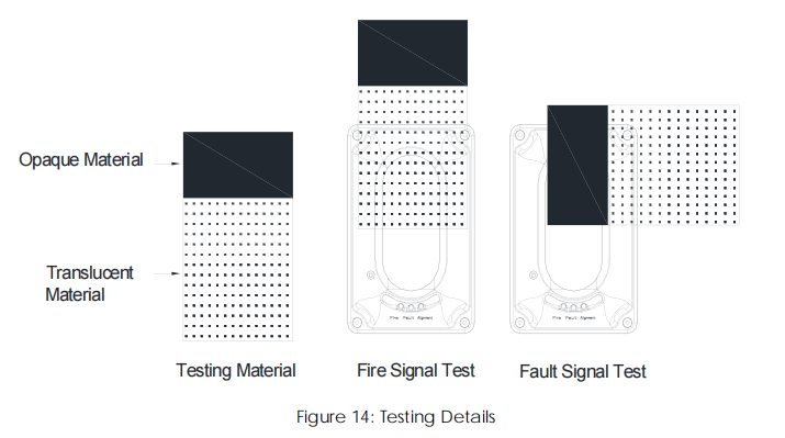
Debugging materials are supporting products of TX7130 and are used for on-site debugging
Features:
Opaque part: Test fault output
Translucent part: Test fire alarm output
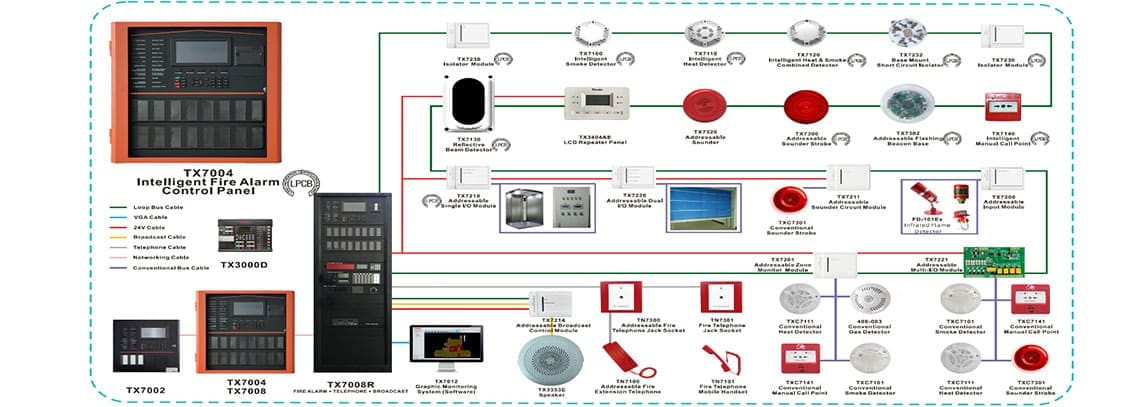
TX7 Serials Addressable Fire Alarm Panels System
A Fire Alarm System is powerful that not only requires a core control panel like the LPCB CE certified TX7004 FACP (Fire Alarm Control Panel), but also needs to be paired with other detectors, modules, and appropriate configurations based on the project’s scale to maximize its effectiveness.
Beam Detector FAQ
What is a beam detector
A beam detector consists of laser transmitter, laser receiver and reflectors.
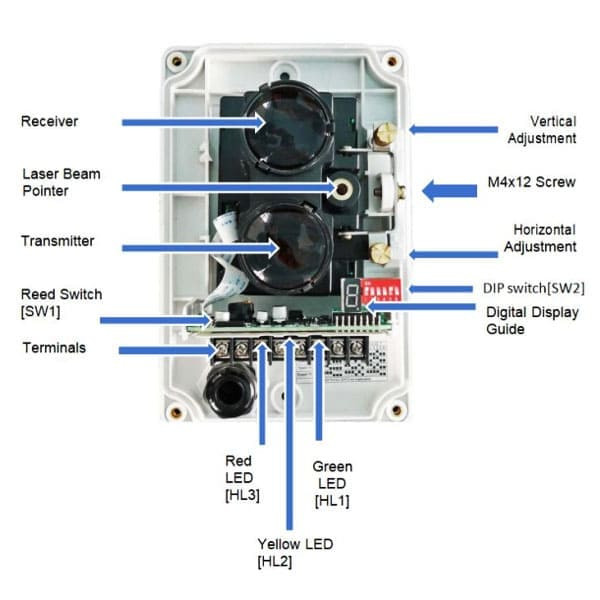
TX7130 Conventional Reflective Beam Detector has built in Laser beam pointing and Digital guide display for real user-friendly alignment method. The Laser beam pointing accurately point the exact location where to mount mirror and with additional digital guide display allows to monitor and guide on the actual light intensity between the mirror and detector which cannot be seen by our naked eye making it more easy and convenient in alignment commissioning.
How to test a beam smoke detector
1, Testing Fire Signal:
1.1, Using supplied Opaque/ Translucent materials, cover-on half of the beam detector using the translucent portion of the material. With less than 30 seconds the Red LED [Fire] will turn on steady, indicating fire signal. [the fire alarm relay [HJ1 and HJ2] will latch to normally close]. Refer to Figure 14.
1.2, Remove the testing material and cut the power off for at least 2 seconds to reset the detector.
2, Testing Fault Signal
2.1, Using supplied Opaque/ Translucent materials, cover-on the half of the beam using the opaque portion of the material. Right after the Yellow LED [Fault] turn on, indicating the fault signal. [The fault alarm relay [GZ1 and GZ2] will latch to normally close]. Refer to Figure 13.
How far apart beam detector
According to the coverage of the beam detector, the horizontal interval between two detectors is seven meters.
for more info about TX7130 beam smoke detector, please contact custom service.
How to check beam detector
1, During the installation phase, two tests are required to check the correctness of the installation: Testing Fire Signal and Testing Fault Signal
2, In daily use, regular inspections must be carried out as specified. Of course, the equipment itself has a self-checking function, as detailed below:
2.1, Automatic Compensation of Light
When dust exists in the working environment of the detector, the emitting window, receiving window and reflector will be covered with dust, which will affect normal operation. in order to solve the problem, TX7130 has the function of automatic compensation of light. When there is dust on windows, the detector can judge the amount of dust, and compensate the received signal through internal program and circuit to ensure the detector can continue to work normally. The detector gives fault signal when dust on the lens and reflector surface reaches a certain level and light compensation reaches the limit for the detector to work normally
2.2, Self-diagnosis on Optical Signal
The detector has functions of checking emitting, receiving and amplifying circuit. When there is faultwith these three parts of circuit during operation, the detector will generate fault information.


